
Manufacturing A Box Transport Mechanism Project
Project Information
Year: Feb. 2020 – May 2020
Group Members: Morsedul Islam, Avinash Persaud, Derrick Paul, Ibrahima Doukoure, John Hahn, Akram Shubon, Juan Tlilayatzi, Raymond Wong
Task
Build a prototype of a mechanical transport mechanism which can move an object over a landing constitutes a transport mechanism. This product is used in the manufacturing industry today that enable optimized manufacturing assembly lines as well as this design is largely used for logistics company.
Design and Analysis Processes

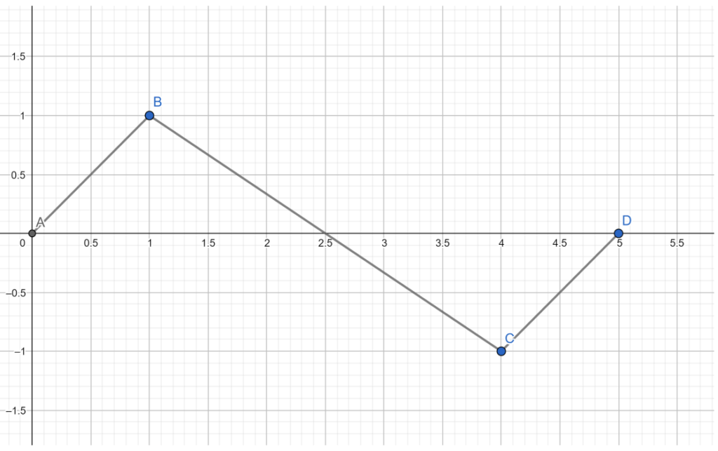
The top figure is the front view of transport mechanism with the several linkages used to transport items. The bottom figure is the representation of the main linkages used during motion.
According the bottom figure, Link AB is the link connecting the blue link in top figure, while link BC is the blue link; link CD is the link adjacent to link AB that also connects link BC. To visualize the motion of the mechanism, the study of dynamics is required which would be used to determine the motions involved. The linkages shown in the bottom figure is a representation of the actual transportation mechanism, From the study of dynamics, a rigid body the type of motion a body experiences may be categorized in two categories, the first is rectilinear motion while the second is termed rotational motion.
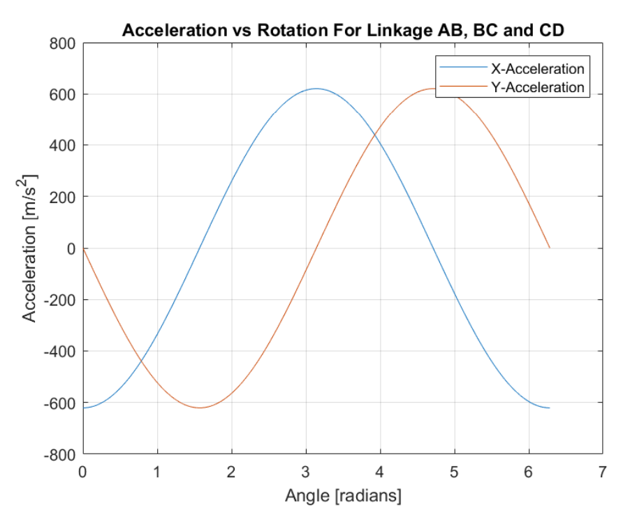
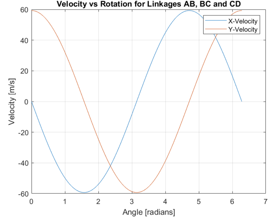
In the top figure, velocity of the mechanism as views from point D. In the bottom figure, acceleration of the mechanism as views from point D.
Computer Aided Manufacturing (CAM) Processes
Crank Design Processes
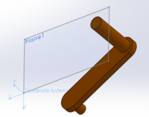
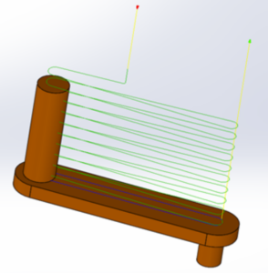
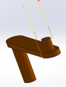
Two cranks were designed in Solidworks, In orderto prepare the crank design for manufacturing process using HSM, two reference planes were placed along the handle and plug of the crank. A coordinate system was created along the left corners of the planes created. A ⅛ inch flat end mill was used to remove material from the surface situated in plane 1. To create a finished pass, the 2D pocket tool was used and the surface of the linkage was selected. A machining profile was then applied through the use of a 2D-pocket by selecting the edges of the crank. This would allow the tool bit machine through the profile providing the necessary geometry for the link.
Plate Design Processes
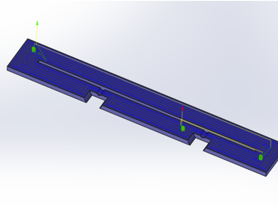
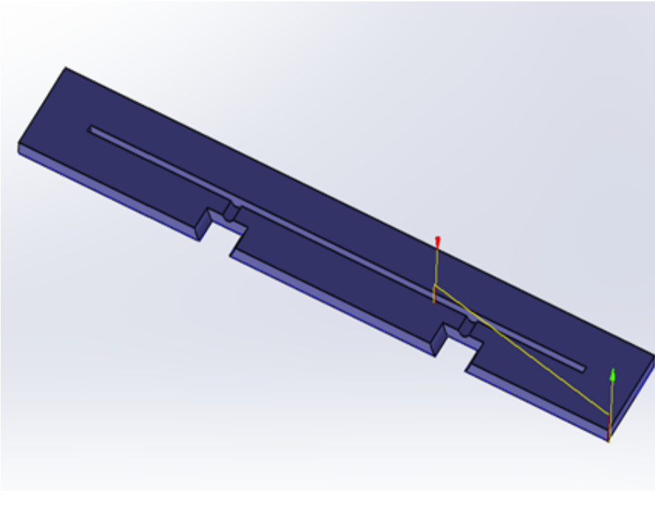
The plate of the transport mechanism was then made in HSM. The plate would serve as the surface that allows the linkages to move and push the box via the slit. A reference plane was created situated at the top surface of the plate. To generate the geometry of the plate, some surfaces needed to be removed; using the 2D-pocket tool, the surface where the coordinate system was placed was chosen as the reference for removal. After selecting the surface, a ⅛ inch flat end mill was chosen to remove undesired material. After removing material, a 2D contour tool was used to machine the profile of the plate. This was done by selecting the edge of the plate and selecting a ⅛ inch flat end mill. This contour tool would remove the excess materials.
Rocker Arm Design Processes
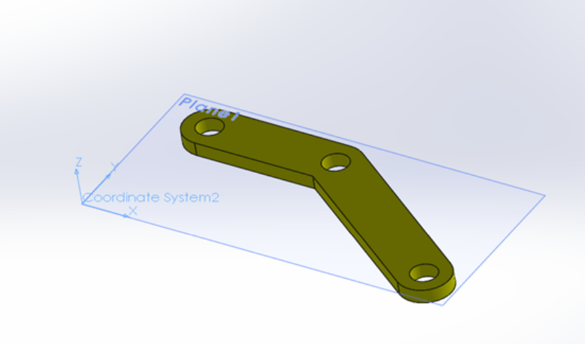
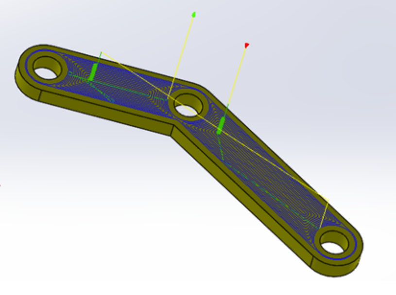
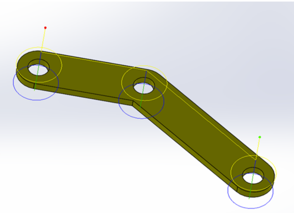
Due to the geometry of the rocker arm some additional measures were taken during the HSM process. A reference plane was created and the coordinate system was placed. The pocket tool was used two times. The first pocket tool was used to construct the geometry of the linkage. The top surface was selected and a flat end mill of 1/64 inch was selected. A second pocket tool was then used to remove any excess material by selecting the sides of the linkage. To produce the holes of the linkage that would connect the other linkages, a drill was used. The diameter of the drill was then set to ⅛ inch while the depth of the hole was set to 5mm.
Body Design Processes
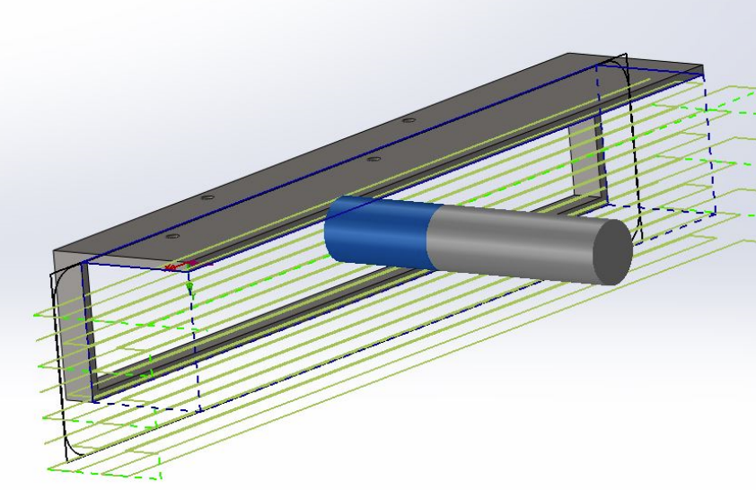
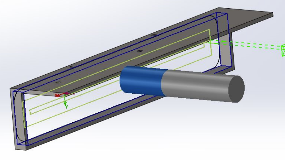
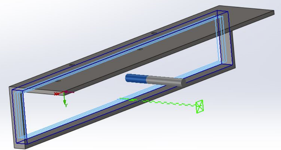
A number of different drill bits were chosen when creating the HSM manufacturing process. Realistically, manufacturing a body of this linear shape could be completed much quicker with a table saw or mill. To replicate this function in HSM, a Rough Mill (T05 – 20 Flat End) was chosen as the first step to cut down the bulk of the material into an L-shape. For bulk removal of material in the hollow face of the L-shape, a Rough Mill (T05 – 20 Flat End) was used. To smoothen the surface, a Contour Mill (T01 – 6 Flat End) was chosen and moved in a curved pattern at the ends to avoid sharp edges as well as the inner face of the hollow portion of the body.
Rocker Arm Design Processes
H- Arm Design Processes
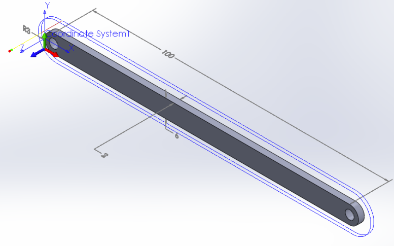
During the HSMworks, the H-Arm starts out as a relatively thin block of metal in proportion to its length. The first operation is to drill two equally sized holes to match the distance between both crank arms. The save milling time, the stock should be cut with the correct length, width, and thickness combined. After cutting a stock with the correct dimensions, one Contour Drill (¼” Flat End Mill) is used to drill both holes and round the edges of both ends.
Grid Design Processes
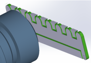
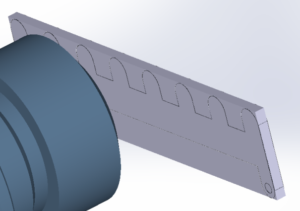
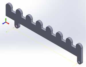
The grid moves the objects resting on the block forward at a consistent pace, equidistant fingers are important to ensure the objects always catch successfully and are moved forward appropriately. The spacing of the fingers on the grid is largely determined by the objects being moved, a design like ours could allow for interchangeable grids. The bottom two holes and the contour were formed with a Rough Mill (1/16” Flat End) the contour of the shape is outlined and then punched out
Assembly Processes
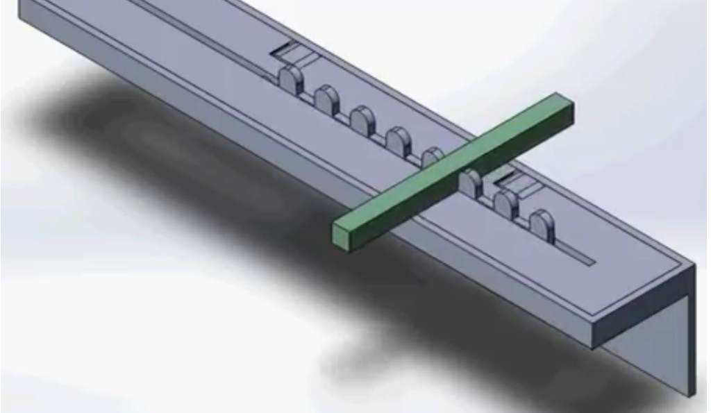
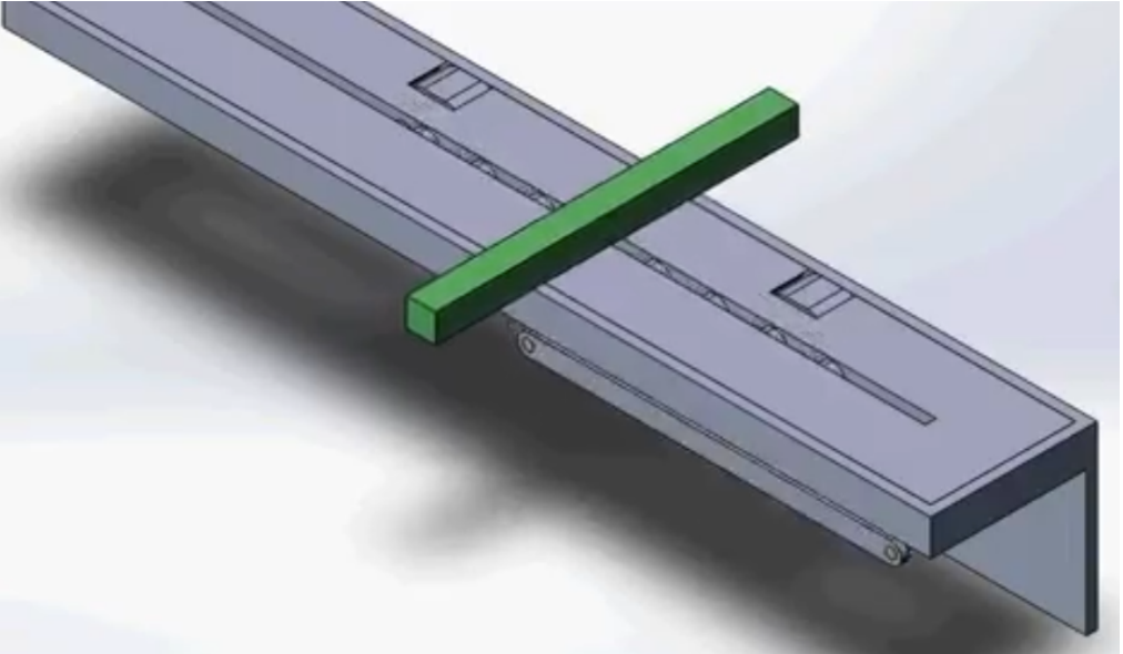
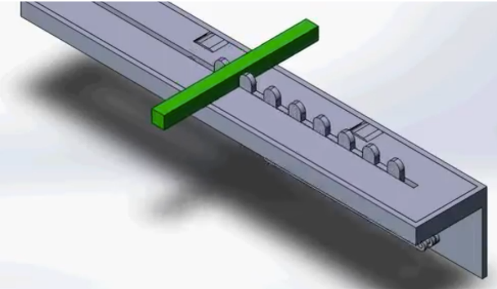
Those figures show the fully assembled transport mechanism in three stages of motion progressively placing the block forwarded with each rotation cycle.
Lets Work Together
The technological revolution is changing aspect of our lives, and the fabric of society itself. it’s also changing the way we learn and what we learn


