Static Analysis of Needle Nose Plier Project
Project Information
Year: Feb. 2020 – May 2020
Group Member: Morsedul Islam
Task
Select a real problem in mechanical design. It should be about a product or part that are very familiar with, from having used it extensively and/or having seen it fail. In order to analyze it using FEM, need to know a lot about it in advance, and should be able to obtain at least one sample of the product or part.
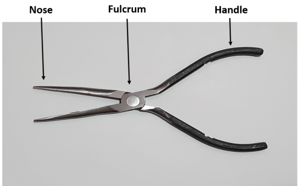
Needle nose plier consists of the nose, the fulcrum in the middle and the handle. The specific needle nose plier used for this project is made of 1045 AISI steel. From this project, I wanted to know how and where a Needle Nose Plier fails. I am to develop analytical techniques which will help to draw reasonable conclusion about the failure of the system and also for redesigning of parts if needed. I planned to find the answers to my questions by conducting an experiment on the plier, and then create a 3D model in SolidWorks to run Finite Element Analysis. Then I would compare the results acquired from my actual experiment and the Finite Element Analysis to check for validity of the model and the analytical solution.
Design and Analysis Processes
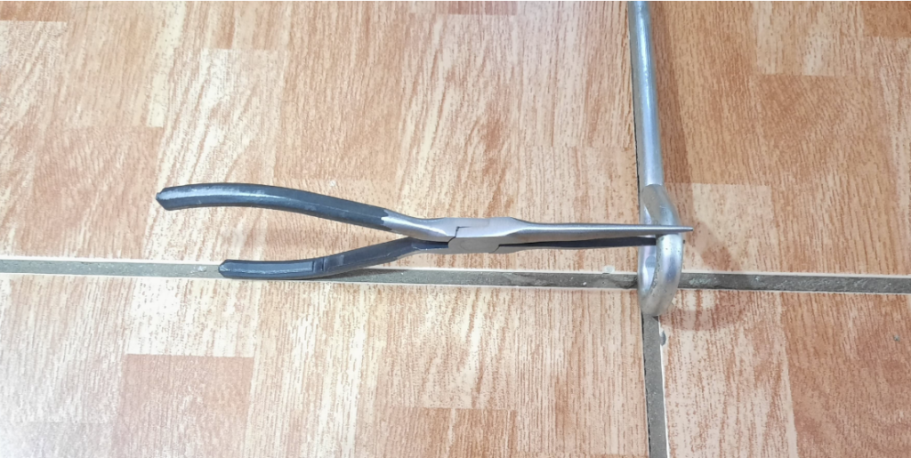
From my prior knowledge I knew that failure would depend on the geometry and the material of the object and also the type of load applied. So, I mimicked the basic plier usage of “gripping” by using an obstruction in between the noses and applying load on the handle. The setup of the experiment conducted, and the free body diagram is shown in the figure.
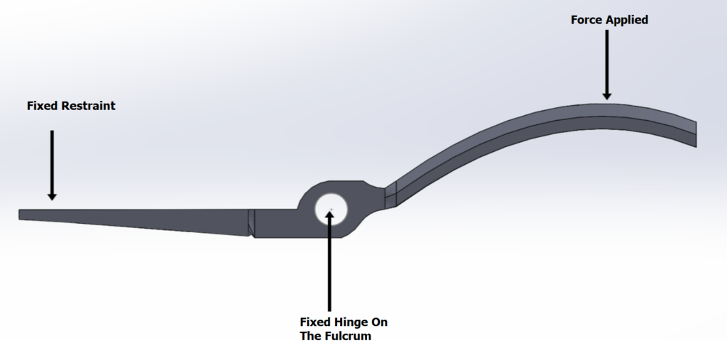
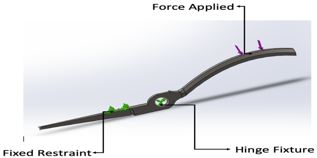
From the setup of the experiment and the free body diagram, I also got the boundary conditions which I will be using for FEA. The boundary conditions acquired are fixed geometry on the face of the nose, fixed hinge on the fulcrum and the force applied on the handle. A visual representation of the boundary conditions is shown in figure.
Solid Modeling Processes
Sketch of the Needle Nose Plier
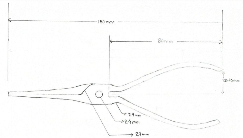
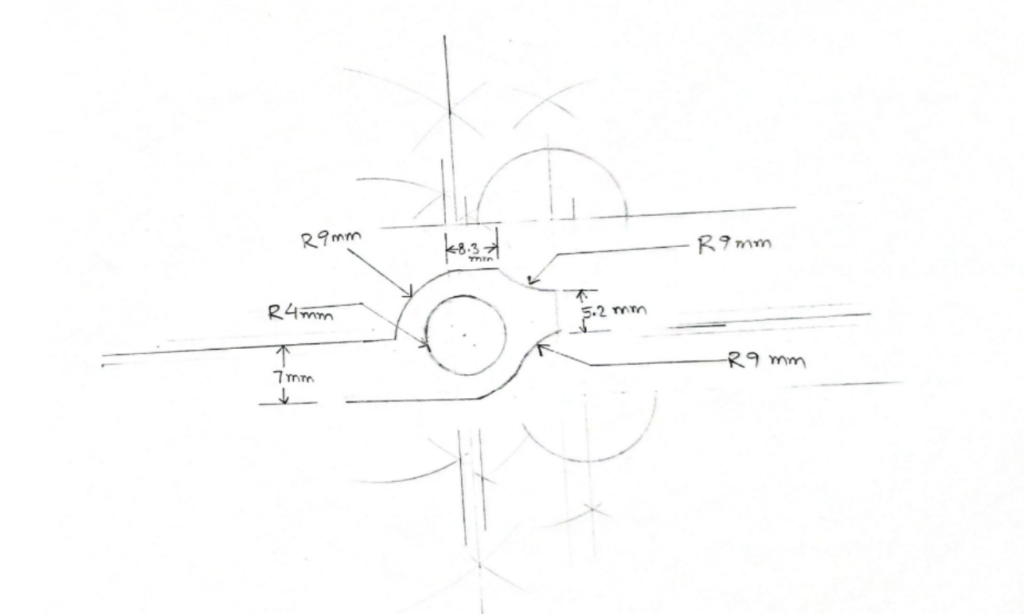
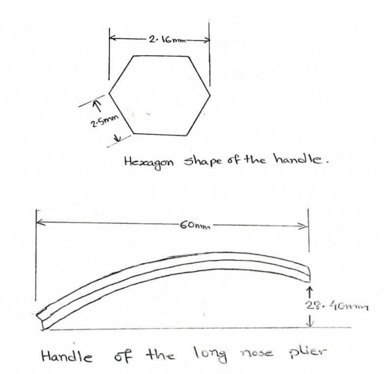
The figure (Top Left) is shown hand sketch of the needle nose plier, figure from bottom left is shown Sketch of the fulcrum and figure from top right is shown sketch of the long nose plier handle.
3D Modeling of Needle Nose Plier
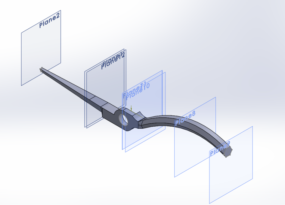
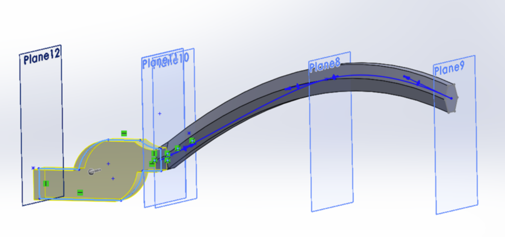
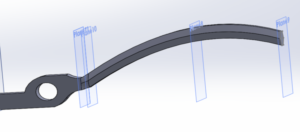
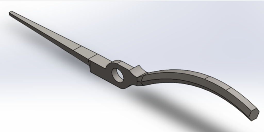
In the top right figure, create the fulcrum of the long nose plier. In the bottom right figure, create the hole of the fulcrum. In the top left figure, isometric view of solid model for one arm of the plier.
Finite Element Analysis (FEA) Process
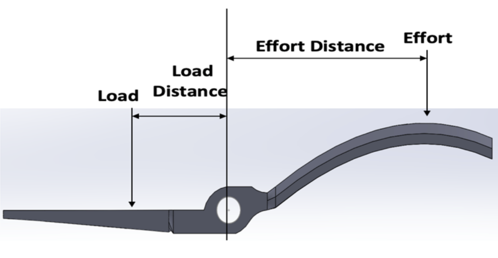
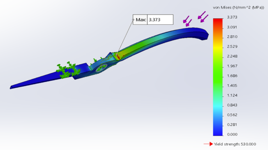
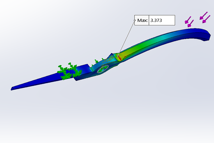
Top figure is shown that Mechanical Advantage schematics. Bottom figure is shown that stress plot with 2nd order mesh and 10mm global element size for 1N force applied.
Modified Design Processes
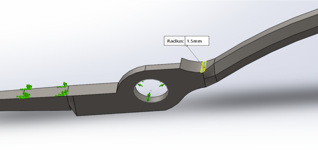
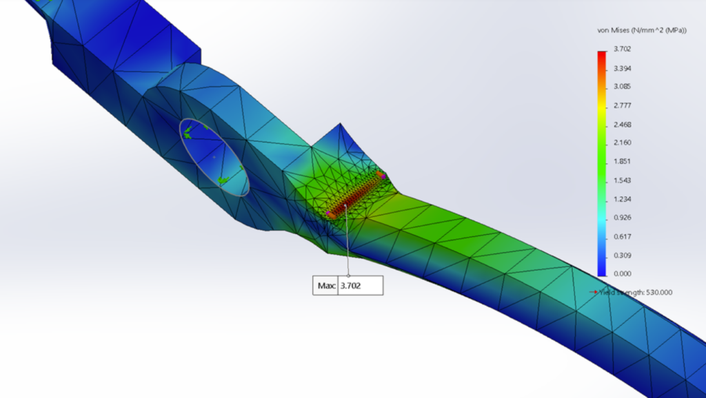
In the top right figure, fillet of radius 1.5mm being applied at the joint. In the bottom right figure, Stress plot with local element size 0.25 mm and global element size of 5mm.
Body Design Processes
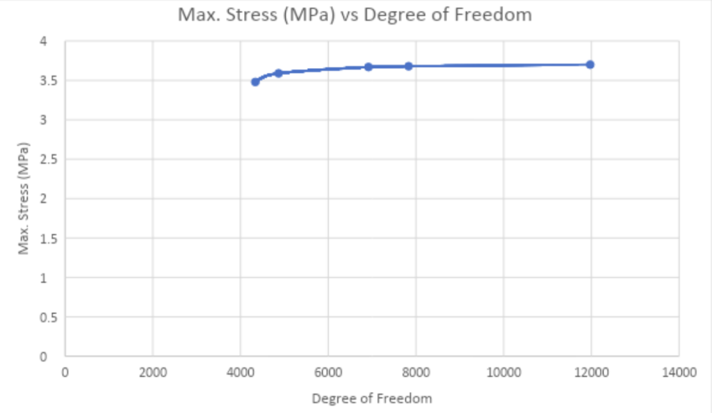
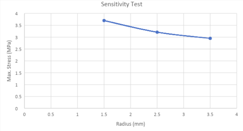
In the top left figure, 2nd order mesh for 1.5mm fillet radius for 5mm global element size varying local element sizes. In the bottom left figure, converged value of maximum stress for different radii.
Rocker Arm Design Processes
FEA Result Analysis
Applied 1N force and ran the simulation for 2nd order mesh with varying global element sizes from 10mm to 1mm. The location of maximum stress and maximum displacement were as predicted i.e. the maximum stress was in the edge between the handle and the fulcrum whereas the maximum displacement was at the tip of the handle. The results obtained were shown diverged. Since, divergence was seen I decided to modify the design. The convergence was obtained for the fillet of 1.5mm radius. I was interested to see the change in the value of maximum stress with the change in the radius of fillet. So, I changed the radius of the fillet from 2.5mm to 3.5mm with the increment of 1mm. The converged value of maximum stress in each case decreased with increase in the fillet radius. This shows that the maximum stress and fillet radius shows almost an exponential relationship. The results obtained for varying radii used to conduct a sensitivity test.
Lets Work Together
The technological revolution is changing aspect of our lives, and the fabric of society itself. it’s also changing the way we learn and what we learn


